Beginners often struggle to connect multiple sensors to an Arduino Mega and write code that makes them work together. The main difficulty is matching the correct pins, power requirements, and libraries.
The answer is a clear, step‑by‑step wiring and coding guide that shows how to set up an ultrasonic distance sensor, an MPU6050 gyroscope, and a servo motor on the same board.
What hardware do you need for an Arduino Mega sensor project
Core board and microcontroller
The foundation of the project is the Arduino Mega 2560. Its 54 digital I/O pins, 16 analog inputs, and multiple hardware serial ports make it ideal for handling an ultrasonic sensor, an MPU‑6050 gyro/accelerometer, and a hobby servo simultaneously. Power the board through a 7‑12 V DC wall adapter connected to the barrel jack, or via a 5 V USB supply if the total current draw stays below 500 mA.
Sensor modules
- HC‑SR04 ultrasonic distance sensor – provides echo‑based ranging up to 4 m. It uses a 5 V supply and two digital pins (trigger and echo).
- MPU‑6050 gyro/accelerometer – a 6‑axis IMU that communicates over I²C. It requires 3.3 V (the Mega’s 3.3 V pin) and the SDA/SCL lines (pins 20 and 21).
- Standard hobby servo – typically a SG90 or MG90S model. It runs from 4.8‑6 V and needs a PWM‑capable digital pin for control.
Power distribution and safety
Because the servo draws peak currents of 500‑800 mA, isolate its power source from the Mega’s 5 V regulator. Use a separate 5 V / 2 A bench supply or a battery pack (four AA cells) wired to the servo’s power line, and connect all grounds together to maintain a common reference. Add a 0.1 µF decoupling capacitor across the MPU‑6050 VCC and GND pins to suppress I²C noise.
Optional tools and accessories
- Breadboard and jumper wires – for quick prototyping without soldering.
- Male‑to‑female Dupont connectors – useful for secure connections to the ultrasonic sensor’s four pins.
- USB cable (type B) – for programming the Mega and for serial monitoring.
- Multimeter – to verify voltage levels and continuity before powering the circuit.
- 3D‑printed or laser‑cut mounting brackets – to position the ultrasonic sensor and MPU‑6050 at fixed angles.
Software support from Qubitpage
The Carpathron Robotics & Coding Windows application can generate and upload firmware that interfaces with the listed sensors. Its AI‑assisted code wizard helps create the I²C initialization for the MPU‑6050 and the pulse‑width modulation routine for the servo, reducing manual coding effort.
Summary checklist
| Item | Typical specification |
|---|---|
| Arduino Mega 2560 | 5 V logic, 54 digital I/O, 16 analog |
| HC‑SR04 ultrasonic | 5 V, 2 digital pins |
| MPU‑6050 IMU | 3.3 V, I²C (SDA/SCL) |
| Hobby servo | 4.8‑6 V, PWM pin |
| Power source for servo | 5 V / 2 A external supply |
| Prototyping accessories | Breadboard, jumper wires, multimeter |
How to wire the ultrasonic distance sensor to the Arduino Mega
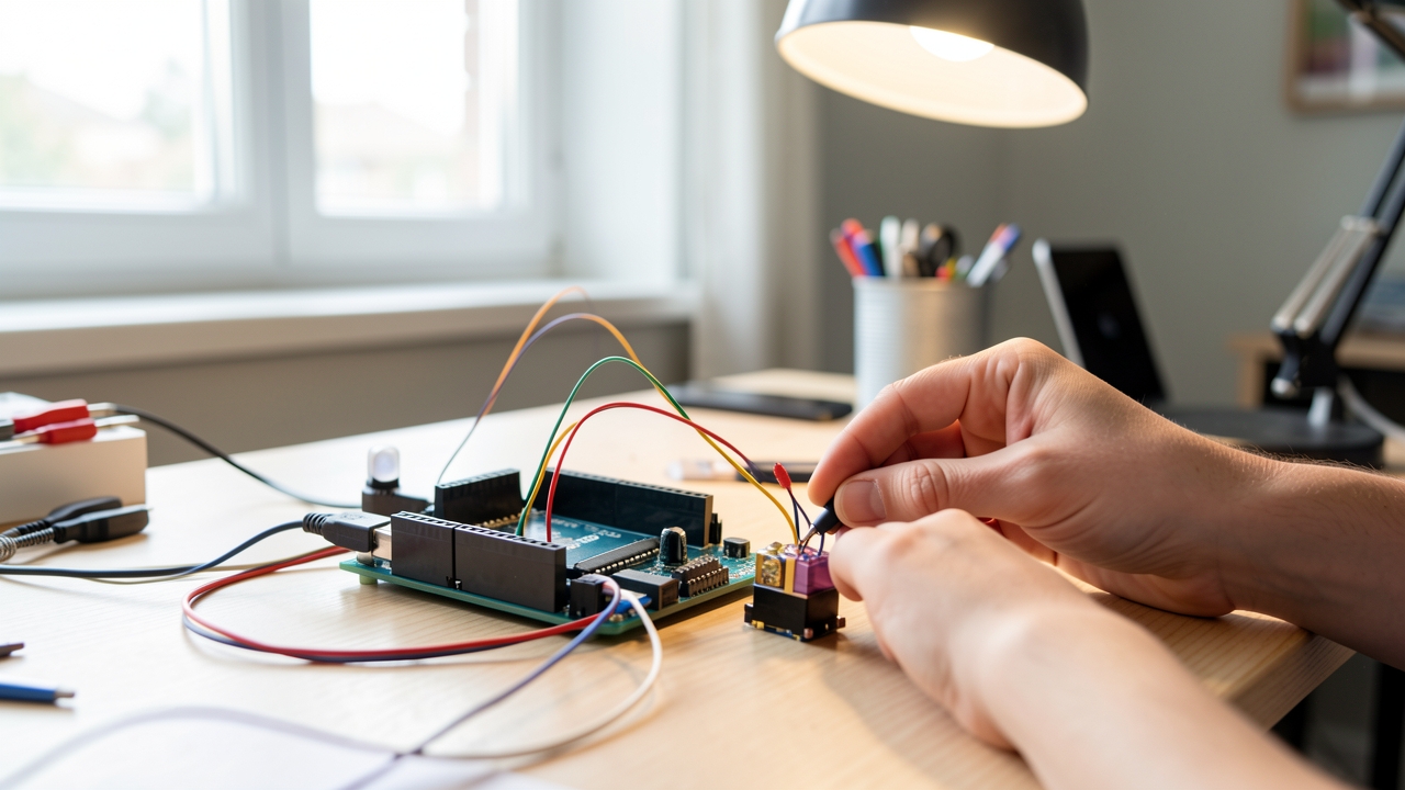
Ultrasonic distance sensors, such as the HC‑SR04, emit a short sound burst and measure the time it takes for the echo to return. The Arduino Mega reads this interval on the Echo pin and converts it to a distance using the speed of sound. Because the Mega provides plenty of digital I/O, you can place the sensor on a breadboard and keep the wiring tidy while prototyping.
- Gather the components. You need an HC‑SR04 module, a standard breadboard, four jumper wires, and the Arduino Mega board.
- Insert the sensor into the breadboard. Align the four pins (VCC, Trig, Echo, GND) with a single row of holes so that each pin sits on its own column.
- Connect VCC to the Mega. Use a red jumper to link the sensor’s VCC pin to the Mega’s
5Vpin (pin 21). The sensor operates at 5 V, so no voltage regulator is required. - Connect GND to the Mega. Attach a black jumper from the sensor’s GND pin to one of the Mega’s ground pins (e.g., GND 1, pin 22). This completes the power circuit.
- Wire the Trig pin. Connect the sensor’s Trig pin to a free digital pin on the Mega, such as
D22. This pin will send the trigger pulse that starts each measurement. - Wire the Echo pin. Connect the Echo pin to another digital pin, for example
D23. The Mega will read the high‑duration signal on this line. - Secure the connections. Double‑check that each jumper is firmly seated in the breadboard and that no wires cross unintentionally. A tidy layout reduces the chance of short circuits during testing.
- Upload a test sketch. Open the Arduino IDE, select the Mega board, and upload a simple sketch that pulses the Trig pin and reads the Echo pin. Verify the serial monitor shows realistic distance values before proceeding to the full project.
When the sensor is powered, the Trig pin receives a 10 µs HIGH pulse, causing the module to emit an 8‑cycle ultrasonic burst at 40 kHz. The Echo pin stays HIGH for the round‑trip time; the Mega measures this interval with pulseIn() and calculates distance by dividing the time by 58 (for centimeters). Using a breadboard lets you experiment with alternative pin assignments without soldering, which is useful if you later integrate the sensor into a larger robot built with Carpathron robotics components.
Tip: Place a 0.1 µF ceramic capacitor between VCC and GND on the breadboard near the sensor. This filters power spikes and improves measurement stability, especially when the Mega drives multiple peripherals simultaneously.
Connecting the MPU6050 gyro/accelerometer to the Mega via I2C
Pin assignment on the Arduino Mega
The MPU6050 uses the I2C bus, which on the Mega is fixed to pins 20 (SDA) and 21 (SCL). Connect the sensor’s SDA line to pin 20 and the SCL line to pin 21. Power the module with 5 V from the Mega’s 5V pin and ground it to the Mega’s GND. The typical wiring table looks like this:
- MPU6050 VCC → Mega
5V - MPU6050 GND → Mega
GND - MPU6050 SDA → Mega
Pin 20 - MPU6050 SCL → Mega
Pin 21
Adding pull‑up resistors
I2C lines are open‑collector; they need pull‑up resistors to the supply voltage. The Mega does not provide internal pull‑ups strong enough for reliable operation with the MPU6050, so place external resistors between each line and 5 V. Values between 4.7 kΩ and 10 kΩ work well. A common practice is to use a single 4.7 kΩ resistor for SDA and another 4.7 kΩ for SCL. Connect the resistor’s one end to the respective line and the other end to the 5V rail on the breadboard.
Verifying the connection
After wiring, open the Arduino IDE and run a simple I2C scanner sketch. The scanner will report the MPU6050’s address (typically 0x68 or 0x69 if the AD0 pin is high). If the address appears, the pull‑ups and pin mapping are correct. If no address is found, re‑check the resistor connections and ensure the sensor is powered.
Integrating with Carpathron Robotics & Coding
The Carpathron Robotics & Coding Windows app can detect the MPU6050 when it is connected via I2C and suggest firmware that reads acceleration and rotation data. Launch the app, select “Add Sensor”, choose “MPU6050”, and let the AI assistant generate the appropriate Arduino sketch. The generated code will include the Wire.begin() call that initializes the Mega’s I2C bus on pins 20/21 automatically.
Sample initialization code
#include <Wire.h>
#include <MPU6050.h>

MPU6050 imu;

void setup() {
  Wire.begin();               // Initializes I2C on pins 20 (SDA) and 21 (SCL)
  Serial.begin(115200);
  imu.initialize();
  if (imu.testConnection()) {
    Serial.println("MPU6050 connection successful");
  } else {
    Serial.println("MPU6050 not detected");
  }
}
void loop() {
  int16_t ax, ay, az, gx, gy, gz;
  imu.getMotion6(&ax, &ay, &az, &gx, &gy, &gz);
  Serial.print("Accel: "); Serial.print(ax); Serial.print(", "); Serial.print(ay); Serial.print(", "); Serial.println(az);
  Serial.print("Gyro: "); Serial.print(gx); Serial.print(", "); Serial.print(gy); Serial.print(", "); Serial.println(gz);
  delay(200);
}
Common troubleshooting tips
- Ensure the MPU6050’s AD0 pin is low if you expect address
0x68. Pull it high to switch to0x69. - Check that the pull‑up resistors are not shorted to ground; a short will keep the lines low and prevent communication.
- If the sensor works on a smaller board (e.g., Uno) but not on the Mega, verify that no other device is using pins 20/21 for a different purpose.
With the correct pins, reliable pull‑ups, and a quick verification step, the MPU6050 can be integrated smoothly into any Arduino Mega project, whether you are building a standalone sensor suite or extending a Carpathron robot with orientation awareness.
Wiring a standard hobby servo to the Arduino Mega
Pinout and basic connections
The typical hobby servo uses three wires: a PWM signal line, a 5 V power line, and a ground reference. Connect the signal wire to any PWM‑capable pin on the Mega, such as pin 9. The red power wire should be tied to a stable 5 V source, while the black or brown ground wire must share the same ground as the Arduino.
Why a separate power supply matters
Servos draw peak currents of 500 mA to 1 A when moving under load. Supplying that current directly from the Mega’s on‑board regulator can cause a brown‑out, resetting the microcontroller and corrupting the program flow. Using an external 5 V supply—preferably a regulated wall‑wart adapter or a dedicated LiPo pack with a 5 V buck converter—keeps the Arduino’s voltage rail stable.
Wire the external supply’s ground to the Mega’s GND pin before connecting the servo ground. This common reference ensures the PWM signal is correctly interpreted by the servo’s control electronics.
Step‑by‑step wiring guide
- Identify the servo’s three leads: signal (usually orange or yellow), power (red), and ground (black or brown).
- Insert a male‑to‑female jumper from the Mega’s pin 9 to the servo’s signal lead.
- Connect the servo’s power lead to the +5 V terminal of the external supply.
- Link the external supply’s ground to the Mega’s GND pin, then attach the servo’s ground lead to the same point.
- Secure all connections with a breadboard or a small terminal block to avoid loose contacts during operation.
Testing the connection
Upload a simple sweep sketch that moves the servo from 0° to 180° in 10° increments, pausing 500 ms between steps. If the servo stalls or the Mega resets, verify that the external power source is delivering at least 1 A and that all grounds are firmly tied together.
For projects that involve multiple servos, cascade the power lines from the same external supply but keep each servo’s signal wire on a separate PWM pin. This layout prevents voltage sag across the shared supply.
Tip: When using a battery pack, add a 100 µF electrolytic capacitor across the supply’s +5 V and GND terminals. The capacitor buffers sudden current spikes and further reduces the risk of brown‑outs.
Integrating with Qubitpage tools
If you plan to control the servo from a remote interface, the Carpathron Robotics & Coding app available on the Microsoft Store can generate the PWM commands and upload firmware directly to the Mega. The same app also supports the Carpathron Avatar, letting you steer a robot car while the servo handles a camera mount.
For additional guidance on power management, see the Products page, which lists recommended power adapters compatible with the Mega and Carpathron accessories.
Complete Arduino Mega code for ultrasonic, gyro and servo
Library inclusion and global objects
Start by loading the three required libraries. NewPing handles the HC‑SR04 ultrasonic sensor, MPU6050 provides orientation data from the MPU6050, and Servo drives a hobby servo. Declare the pins for trigger and echo, the maximum distance you expect, and create the NewPing instance. Then instantiate the MPU6050 object and a Servo object for the motor.
#include <NewPing.h>
#include <MPU6050.h>
#include <Wire.h>
#include <Servo.h>

// Ultrasonic pins
const uint8_t TRIG_PIN = 22;
const uint8_t ECHO_PIN = 23;
const unsigned int MAX_DISTANCE = 200; // cm

NewPing sonar(TRIG_PIN, ECHO_PIN, MAX_DISTANCE);

// MPU6050
MPU6050 imu;

// Servo
Servo myServo;
const uint8_t SERVO_PIN = 9;
Setup routine
In setup() initialise serial communication for debugging, start I2C, and begin the MPU6050. Verify the sensor connection; if it fails, print an error and halt. Attach the servo to its pin and set an initial position of 90° (neutral). The ultrasonic sensor does not require explicit initialisation beyond the NewPing constructor.
void setup() {
  Serial.begin(115200);
  Wire.begin();

  // Initialise MPU6050
  if (!imu.begin()) {
    Serial.println(F("MPU6050 connection failed"));
    while (1);
  }
  imu.calcGyroOffsets(true);

  // Attach servo
  myServo.attach(SERVO_PIN);
  myServo.write(90);

  Serial.println(F("System ready"));
}
Main loop – reading sensors and controlling the servo
The loop reads distance, pitch, and roll, then maps the distance to a servo angle. The ultrasonic reading uses sonar.ping_cm(). For the MPU6050, imu.update() refreshes the sensor, and imu.getAngleX() and imu.getAngleY() provide pitch and roll in degrees. The distance is constrained between 5 cm and 150 cm, then scaled to a 0‑180° range for the servo. Finally, the values are printed for monitoring.
void loop() {
  // Ultrasonic distance (cm)
  unsigned int distance = sonar.ping_cm();
  if (distance == 0) distance = MAX_DISTANCE; // no echo

  // MPU6050 orientation
  imu.update();
  float pitch = imu.getAngleX(); // X‑axis tilt
  float roll  = imu.getAngleY(); // Y‑axis tilt

  // Map distance to servo angle
  distance = constrain(distance, 5, 150);
  int servoAngle = map(distance, 5, 150, 0, 180);
  myServo.write(servoAngle);

  // Debug output
  Serial.print(F("Dist: "));
  Serial.print(distance);
  Serial.print(F(" cm | Pitch: "));
  Serial.print(pitch);
  Serial.print(F("° | Roll: "));
  Serial.print(roll);
  Serial.print(F("° | Servo: "));
  Serial.println(servoAngle);

  delay(100);
}
Integrating with Qubitpage robotics tools
If you plan to run the Mega code on a Carpathron robot, you can upload the sketch via the Carpathron Robotics & Coding desktop agent. The agent’s AI assistance can suggest parameter tweaks for the servo range or sensor thresholds, speeding up iteration on the hardware side.
Feature comparison of sensor libraries and alternatives
The Arduino ecosystem offers several libraries that simplify working with ultrasonic range finders, IMU modules and hobby servos. Choosing the right one depends on how much memory your Mega can spare, the required update frequency, and the complexity of the surrounding code. Below is a concise comparison of the most common choices: NewPing for ultrasonic sensors, Ultrasonic (a lightweight alternative), Jeff Rowberg’s MPU6050 library for gyroscope/accelerometer data, and the built‑in Servo library.
| Library | Ease of use | Required RAM (bytes) | Typical update rate | Typical applications |
|---|---|---|---|---|
| NewPing | High – single‑function calls (e.g., ping_cm()) |
~30 | Up to 30 Hz (depends on sensor echo time) | Obstacle avoidance, distance‑based triggers |
| Ultrasonic | Medium – requires manual timing with pulseIn() |
~15 | 10–20 Hz (limited by pulseIn() blocking) |
Simple range checks, educational demos |
| MPU6050 (Jeff Rowberg) | Medium – initialization routine and getMotion6() call |
~120 (includes FIFO buffer) | Up to 200 Hz (depends on I2C speed) | Stabilization, motion tracking, robot orientation |
| Servo (built‑in) | High – Servo.attach() and write() are straightforward |
~30 per servo instance | 50 Hz (default PWM refresh) | Arm actuation, steering, camera pan/tilt |
When memory is at a premium, the lightweight Ultrasonic library wins, but its blocking pulseIn() call can stall other tasks. NewPing adds non‑blocking support and automatic timeout handling, making it a better fit for projects that also read IMU data or drive servos concurrently.
The MPU6050 library by Jeff Rowberg is the de‑facto standard for raw sensor access. It provides calibrated readings, interrupt support and FIFO handling, which are essential for smooth robot navigation. On an Arduino Mega, the extra RAM consumption is acceptable, especially when the robot runs multiple peripherals such as the Carpathron Avatar (Carpathron robotics) or the Windows‑based Carpathron Robotics & Coding app (product page).
The native Servo library is reliable for up to 12 simultaneous servos on the Mega. If you need higher precision or chained motion profiles, consider using the ServoTimer2 variant, but that adds a few hundred bytes of RAM.
In practice, a balanced setup for the Arduino Mega sensor project uses NewPing for the HC‑SR04, Jeff Rowberg’s MPU6050 for orientation, and the built‑in Servo library for the steering motor. This combination stays well under the Mega’s 8 KB SRAM limit while delivering sub‑30 ms sensor updates and smooth 50 Hz servo control.
Frequently asked questions
How do I power multiple sensors on an Arduino Mega without overloading the board?
Connect the sensor VCC lines to an external 5 V supply that can provide the combined current, and link the grounds to the Mega’s GND. Use a common‑mode choke or a small decoupling capacitor (0.1 µF) near each sensor to suppress noise. Keep the Mega’s 5 V pin only for low‑current devices such as pull‑up resistors or status LEDs.
What is the correct I2C address for the MPU6050 on a Mega?
The MPU6050 defaults to the 7‑bit address 0x68 when the AD0 pin is low. If you solder the AD0 pin high, the address changes to 0x69. Verify the address with an I2C scanner sketch before initializing the sensor in your code.
Can I use the same PWM pin for more than one servo?
The Arduino Mega provides dedicated PWM channels, but each servo requires its own timer output to maintain precise pulse widths. Sharing a single PWM pin will cause jitter and unpredictable positions. Use separate pins (e.g., pins 2‑13) or a servo driver board that handles multiple servos on a single I2C bus.
Why does the ultrasonic sensor give erratic readings and how to fix it?
Cross‑talk between multiple ultrasonic modules or reflections from nearby surfaces can produce spurious echoes. Trigger each sensor sequentially with at least a 60 ms delay and add a short delayMicroseconds(10) after the trigger pulse. Shield the echo line with a 100 Ω resistor and place a 0.1 µF capacitor across VCC and GND to reduce power ripple.
Is it safe to run the servo directly from the Mega’s 5 V regulator?
The on‑board regulator is rated for only a few hundred milliamps, while a typical hobby servo draws 500‑800 mA under load. Power the servo from a separate 5 V supply capable of at least 2 A and connect its ground to the Mega’s ground to maintain a common reference. This prevents voltage sag that could reset the board or cause erratic behavior.
Wrap‑up and next steps
In this guide we connected an HC‑SR04 ultrasonic sensor, an MPU‑6050 gyro/accelerometer, and a standard SG90 servo to an Arduino Mega, calibrated the readings, and combined them in a single loop that updates distance, orientation, and position in real time. The key points are to power the sensors from the 5 V rail, use separate I²C pull‑up resistors for the gyro, and map the servo angle to the measured distance for smooth obstacle avoidance.
After verifying the serial output, upload the sketch and test the robot on a flat surface. Adjust the servoMin and servoMax constants to match your servo’s mechanical limits, and fine‑tune the gyro’s filter coefficients if the orientation drifts. For more complex behaviors, consider adding conditional logic that triggers the servo only when the ultrasonic reading falls below a safety threshold.
When you are ready to expand the project—perhaps by adding Wi‑Fi telemetry or integrating AI‑assisted code generation—explore the tools offered by Qubitpage. Discover the Carpathron Robotics & Coding app to streamline firmware updates and experiment with robot control from your desktop.