Many makers want a simple, low‑cost robot car that streams live video and can be controlled over Wi‑Fi. The ESP32‑CAM module is ideal because it combines a camera, Wi‑Fi, and a microcontroller in one tiny board.
In this guide we show how to assemble the hardware, flash firmware, and use Carpathron Remote and Carpathron Robotics & Coding to get a fully functional robot car that you can drive from anywhere.
Choosing the Right ESP32‑CAM Module
When building a robot car that streams video and responds to remote commands, the core of the system is the camera‑on‑board ESP32‑CAM module. The ESP32‑CAM family comes in several variants, each with a slightly different pinout and flash configuration. The most common models are the ESP32‑CAM‑M10, ESP32‑CAM‑M2, and ESP32‑CAM‑M5. All three use the same ESP32‑S3 or ESP32‑D0S2 core, but the M10 and M5 include a 4 MP OV2640 sensor, while the M2 uses a lower‑resolution OV7725. For a robot car that requires high‑definition video for navigation and obstacle avoidance, the M10 or M5 is preferred because the 4 MP sensor provides sharper images and better low‑light performance.
Pin Layout and Power Considerations
Each ESP32‑CAM module exposes a 20‑pin header. Key pins include GPIO 0 (boot mode), GPIO 2 (camera reset), GPIO 4 (camera power down), and the camera data pins GPIO 12–15. The module also has a VSYNC and HREF pin for frame synchronization, which can be useful for advanced image processing. Power is supplied through the VDD pin, which must be a regulated 5 V source. The ESP32 core itself runs at 3.3 V, so the module contains an on‑chip regulator that steps down the 5 V input. If you are driving other peripherals directly from the ESP32‑CAM, consider adding a 3.3 V logic level shifter to protect the camera sensor and avoid voltage mismatches.
Why ESP32‑CAM Is Ideal for a Robot Car
The ESP32‑CAM offers a compact footprint, integrated Wi‑Fi, and sufficient processing power to run a lightweight object‑detection model. Its camera interface is compatible with the open Carpathron Robot Protocol, allowing the robot to stream MJPEG frames over HTTP. Because the module can be controlled entirely through GPIOs, you can connect motor drivers, Li‑Ion battery packs, and a small OLED display without needing an external microcontroller. The 5 V power requirement matches standard Li‑Ion battery packs, simplifying power distribution on the car chassis.
Getting Started with Carpathron Robotics & Coding
Once you have selected the appropriate ESP32‑CAM variant, the next step is to load the Carpathron Robotics & Coding firmware. The Windows app, available for free on the Microsoft Store here, guides you through firmware selection, board detection, and upload. The app’s AI assistant can generate the necessary configuration files, set up the Wi‑Fi credentials, and even help you write a custom control script that communicates with the Carpathron Remote app on your phone. For more advanced projects, the Carpathron project page offers sample code for integrating the robot with Meta Muse models and other platforms.
In summary, choosing the ESP32‑CAM M10 or M5 provides the best balance of image quality, processing capability, and power efficiency for a robot car. By following the pin‑out guidelines and using the supplied 5 V power rail, you can build a reliable, Wi‑Fi‑controlled vehicle that streams live video and responds to remote commands with minimal latency.
Hardware Assembly and Wiring
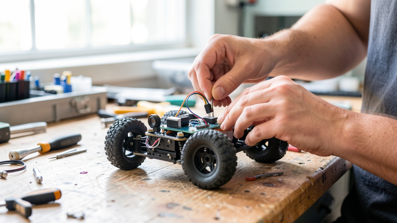
The ESP32‑CAM robot car is built on a lightweight aluminum chassis that houses a 2 × 2 inch motor mount, a 5 V/2 A battery pack, and a 5 mm camera bay. The chassis is designed for easy access to the motor driver headers and the ESP32‑CAM’s pin‑out. Begin by mounting the two DC motors onto the motor brackets using the supplied M3 screws. Align the motor shafts with the gear pulleys on the chassis to ensure a straight line of travel.
Motor Driver Integration
We recommend the L298N dual H‑bridge module for its 2 A per channel rating. Connect the motor driver’s IN1/IN2 pins to GPIO 12 and 13 on the ESP32‑CAM, and IN3/IN4 to GPIO 14 and 27. The ENA and ENB pins should be tied to 5 V to keep the motors fully enabled. The motor driver’s VCC and GND pins connect to the 5 V and GND rails of the chassis battery. Use a 100 µF electrolytic capacitor across VCC and GND near the driver to suppress voltage spikes during acceleration.
ESP32‑CAM to Camera Bay
The ESP32‑CAM’s built‑in OV2640 camera is mounted on the chassis top plate. Connect the camera’s power pin (3.3 V) to the ESP32‑CAM’s 3.3 V output. Ground the camera to the ESP32‑CAM’s GND. The camera’s I2C pins (SDA, SCL) are already wired internally to the ESP32‑CAM’s I2C bus; no external connections are required. Ensure the camera lens is oriented forward and that the bay’s rubber gasket is seated to prevent dust ingress.
Power Distribution
The 5 V battery pack (Li‑Po 3.7 V 1000 mAh) is boosted to 5 V by a 5 V step‑up regulator (e.g., AMS1117). Route the regulator’s output to the motor driver VCC and the ESP32‑CAM’s 5 V pin. The ESP32‑CAM’s 3.3 V pin is regulated by its internal LDO. Connect the battery’s negative terminal to the chassis ground rail, and then to the ESP32‑CAM’s GND and the motor driver GND. Use a 10 kΩ pull‑up resistor on the ESP32‑CAM’s EN pin to keep the module powered when the battery is connected.
Tip: When handling the Li‑Po battery, always use a protective case and keep it away from metal objects to avoid short circuits.
For a visual reference, see the wiring diagram in the Carpathron Robotics & Coding documentation. Once assembled, test the motor controls by uploading the sample Carpathron firmware and issuing a forward command. Verify that the camera stream is active by navigating to the ESP32‑CAM’s IP address in a browser. If the motors do not respond, double‑check the GPIO assignments and ensure the motor driver’s enable pins are powered. Proper grounding and secure connections are critical for reliable operation and to prevent data corruption during live video streaming.
Firmware Development with Carpathron Robotics & Coding
Carpathron Robotics & Coding is a free Windows application available on the Microsoft Store that simplifies firmware development for ESP32‑CAM modules. The app automatically detects the camera board when it is connected via USB, presents a code editor with syntax highlighting, and offers an AI assistant that suggests code snippets and best‑practice patterns for common tasks such as Wi‑Fi initialization and camera streaming. By leveraging the built‑in compiler, developers can build and flash firmware in a single workflow without the need for external toolchains.
Below is a concise, step‑by‑step guide to creating a minimal firmware that connects the ESP32‑CAM to a Wi‑Fi network, starts an MJPEG video stream, and exposes a simple HTTP endpoint for remote control. The example demonstrates how to integrate the AI assistant for code completion, ensuring that even novice users can produce reliable firmware.
- Install the App: Download Carpathron Robotics & Coding from the Microsoft Store and launch it on Windows 10/11. The first run will prompt you to install the ESP-IDF runtime; accept the defaults.
- Connect the ESP32‑CAM: Plug the module into a USB‑to‑serial adapter and connect the adapter to the PC. The app’s device list will automatically show the ESP32‑CAM; select it and click Detect.
- Start a New Project: Choose New Project and select the ESP32‑CAM template. The editor opens with a skeleton C file containing the necessary includes and a
main()function. - Use AI Code Suggestions: Place the cursor inside the
main()function and typewifi. The AI assistant will propose a complete Wi‑Fi initialization block. Accept the suggestion, then replace the placeholder SSID and password with your network credentials. - Add Camera Streaming: Type
cameraand let the AI insert the camera configuration and initialization code. Verify that thestartCamera()function is called after Wi‑Fi connects. This sets up an MJPEG server on port 80. - Implement a Simple Control Endpoint: Type
http serverto generate a basic HTTP server skeleton. Add a route, e.g.,/cmd, that parses query parameters to adjust motor PWM values. The AI can suggest the necessary GPIO and PWM setup. - Build and Flash: Click the Build & Flash button. The app compiles the firmware, shows the console output, and uploads the binary to the ESP32‑CAM. A progress bar confirms successful flashing.
- Verify Operation: Open a browser and navigate to
http://ESP32‑CAM_IP/streamto view the live video. Use Carpathron Remote to send/cmd?left=100&right=100requests and observe the motors respond.
With these steps, you can quickly prototype an ESP32‑CAM robot car, harnessing the AI‑powered code assistant to accelerate development and reduce errors. For extended functionality, explore the Carpathron robotics ecosystem or contact contact@qubitpage.com for support.
Configuring Live Video Streaming
After the ESP32‑CAM is powered and the camera module is seated, the first step to a functional video stream is to enable the built‑in HTTP server that serves MJPEG frames. The firmware in the Carpathron Robotics & Coding package includes a lightweight esp_camera_webserver example that can be adapted for the robot car. The following steps outline the configuration process.
1. Selecting Resolution and Frame Rate
The ESP32‑CAM offers several predefined resolutions. For a balance between bandwidth and clarity, FRAMESIZE_QVGA (320×240) is a common choice. In the camera_config_t structure, set:
camera_config_t config = {
  .pin_pwdn = PWDN_GPIO_NUM,
  .pin_reset = RESET_GPIO_NUM,
  .pin_xclk = XCLK_GPIO_NUM,
  .pin_sscb_sda = SIOD_GPIO_NUM,
  .pin_sscb_scl = SIOC_GPIO_NUM,
  .pin_d7 = Y9_GPIO_NUM,
  .pin_d6 = Y8_GPIO_NUM,
  .pin_d5 = Y7_GPIO_NUM,
  .pin_d4 = Y6_GPIO_NUM,
  .pin_d3 = Y5_GPIO_NUM,
  .pin_d2 = Y4_GPIO_NUM,
  .pin_d1 = Y3_GPIO_NUM,
  .pin_d0 = Y2_GPIO_NUM,
  .pin_vsync = VSYNC_GPIO_NUM,
  .pin_href = HREF_GPIO_NUM,
  .pin_pclk = PCLK_GPIO_NUM,
  .xclk_freq_hz = 20000000,
  .ledc_timer = LEDC_TIMER_0,
  .ledc_channel = LEDC_CHANNEL_0,
  .pixel_format = PIXFORMAT_JPEG,
  .frame_size = FRAMESIZE_QVGA,
  .jpeg_quality = 12,
  .fb_count = 2
};
Adjust frame_size to FRAMESIZE_VGA or FRAMESIZE_SVGA if higher resolution is required, keeping in mind the increased bandwidth.
2. Configuring the HTTP Server Port
The default server listens on port 80. To avoid conflicts on a busy network, change server.on to a custom port, for example 8080:
WiFiServer server(8080);
server.begin();
Update the index.html reference in the firmware to point to http://<ESP32_IP>:8080/stream when testing.
3. Starting the Stream
In the main loop, the server serves the MJPEG stream via the /stream endpoint. The Carpathron firmware automatically handles frame capture and HTTP headers. Compile and flash the modified sketch using PlatformIO:
pio run --target upload
Once the device restarts, connect to the same Wi‑Fi network and open a browser. Enter http://<ESP32_IP>:8080/stream. The browser should display a continuous video feed. If the feed is blank, check that the camera pins are correctly connected and that the Wi‑Fi credentials in config.h match the network.
4. Integrating with Carpathron Remote
The Carpathron Remote app can consume the MJPEG stream by pointing its camera view to the same URL. This allows synchronized video and control from a single interface.
Tip: When testing on a mobile device, use a lightweight browser like Firefox or Chrome. If latency is high, reduce
jpeg_qualityor switch toFRAMESIZE_QVGAto lower the data rate.
With the stream configured, the robot car is ready for remote operation and can be extended to include additional sensors or control logic as needed. For further assistance, contact contact@qubitpage.com.
Remote Control via Carpathron Remote
To operate the ESP32‑CAM robot car from a distance, install the Carpathron Robotics & Coding Windows application on the controlling PC. Launch the installer from the Microsoft Store link, accept the license, and let the setup copy the executable to C:\Program Files\Carpathron\Remote. Once installed, run CarpathronRemote.exe and follow the wizard to create a one‑time password (OTP). The OTP is a 6‑digit code displayed on the PC screen; it must be entered on the ESP32‑CAM device within 30 seconds to establish a secure session.
Generating the One‑Time Password
Open the Carpathron Remote console and click Create OTP. The tool will generate a random 6‑digit number and display a QR code. Scan the QR code with the ESP32‑CAM’s camera or type the number directly into the device’s web interface at http://192.168.4.1/otp. The OTP is valid for a single connection; after the first successful handshake, the device will store a session key for subsequent commands.
Using the SSH Terminal
With the session key in place, the remote PC can send motor commands through an SSH terminal. Open the built‑in PowerShell or Command Prompt and type:ssh -p 22 esp32@192.168.4.1
The password prompt will request the OTP. Enter the 6‑digit code, and the SSH session will authenticate. Once logged in, the ESP32‑CAM runs a lightweight shell that accepts simple motor directives. For example, to move forward at 50% speed, type:motor forward 50
To turn right, use:motor turn right 30
The ESP32‑CAM acknowledges each command with a status message. This text‑based interface allows developers to script complex maneuvers or integrate the robot into larger automation workflows.
Integrating with Carpathron Remote
Carpathron Remote provides a graphical layer over the SSH commands. In the remote interface, select the ESP32‑CAM device from the device list, then choose the Motor Control panel. The panel exposes sliders for speed and direction, which translate into the same motor commands sent via SSH. This dual‑mode control is useful for quick prototyping and for debugging during development. For advanced users, the remote console can be extended by adding custom scripts under ~/.carpathron/scripts, allowing batch execution of motor sequences.
For detailed troubleshooting or to request assistance, contact the support team at contact@qubitpage.com or visit the contact page. The Carpathron Remote documentation is available on the Remote Control page, which also includes links to related projects such as the Carpathron robotics initiative and the QuBIOS firmware.
Performance Checklist for Your Robot Car
Before deploying the ESP32‑CAM robot car in a field test, verify that each subsystem meets the project’s operational requirements. The checklist below focuses on four critical metrics that influence mission success: battery endurance, image fidelity, command latency, and wireless reach. Each item is scored against the minimum thresholds recommended for typical hobbyist and prototype deployments.
| Metric | Target Value | Typical Component | Verification Method |
|---|---|---|---|
| Battery Life | ≥ 2 hours at 50 % load | 18650 Li‑ion pack (3.7 V, 3000 mAh) | Measure current draw with a USB multimeter while running the Carpathron firmware at 30 fps. |
| Camera Resolution | ≥ 640 × 480 pixels | OV2640 sensor on ESP32‑CAM | Capture a JPEG stream and inspect dimensions in an image viewer. |
| Latency | ≤ 120 ms (command to motor response) | ESP32‑CAM Wi‑Fi (802.11b/g/n) | Ping the microcontroller from a PC and record round‑trip time. |
| Control Range | ≥ 30 m line‑of‑sight | ESP32‑CAM with external antenna | Move the remote control device to the edge of the signal and confirm command reception. |
Each row in the table represents a measurable outcome. For battery life, a 3000 mAh pack should sustain the car for at least two hours under moderate motion and streaming. If the measured duration falls short, consider a higher capacity pack or a low‑power motor driver.
Camera resolution is dictated by the OV2640 sensor. The Carpathron Robotics & Coding app allows you to set the frame size via the Carpathron app. Verify that the chosen resolution does not exceed the ESP32’s 3.2 MB RAM limit, which would cause frame drops.
Latency is critical for real‑time steering. The Carpathron Remote, available at /remote, uses MQTT over Wi‑Fi. Ensure the network is free of interference and that the ESP32’s Wi‑Fi module is operating on the 2.4 GHz band to keep latency below 120 ms.
Control range depends on antenna quality and environmental obstructions. The ESP32‑CAM’s default PCB antenna is limited; attaching a 2.4 GHz external antenna can extend reach beyond 30 m. Test the range in the intended deployment area, such as a warehouse or outdoor field.
After completing the checklist, document the results in a simple log. This record will help you compare successive builds, identify regressions, and guide future hardware upgrades. If any metric fails, revisit the corresponding component in the Carpathron robotics design and iterate until all thresholds are satisfied.
By systematically evaluating battery endurance, image quality, latency, and range, you can ensure that the ESP32‑CAM robot car performs reliably in real‑world scenarios. This disciplined approach aligns with Qubitpage’s focus on engineering precision and user‑centric design.
Frequently asked questions
What power supply do I need for the ESP32‑CAM robot car?
The ESP32‑CAM requires a stable 5 V supply for the camera module and a separate 3.3 V regulator for the microcontroller. A 5 V 2 A USB‑C power bank or a 5 V 3 A wall charger is sufficient for the camera and motors. Use a buck converter (e.g., AMS1117) to step down from 5 V to 3.3 V for the ESP32‑CAM, ensuring a minimum of 500 mA current capacity to avoid brownouts during Wi‑Fi bursts.
How do I avoid latency when streaming video?
Configure the ESP32‑CAM to stream at 640×480 resolution and 30 fps, which balances quality and bandwidth. Enable MJPEG compression in the Arduino sketch and set the HTTP server to use chunked transfer encoding. On the client side, use a lightweight viewer such as VLC or a custom web page that buffers frames and displays them with minimal delay.
Can I use a different motor driver than the L298N?
Yes. Any H‑bridge capable of 12 V and 2 A per channel can replace the L298N. For example, the DRV8833 or TB6612FNG provide higher efficiency and lower heat dissipation. Update the Arduino code to match the new driver’s pinout and enable PWM speed control via the ESP32‑CAM’s 12‑bit DAC outputs.
Is the Carpathron Remote compatible with Linux?
The Carpathron Remote is a cross‑platform desktop application available on the Microsoft Store and as a portable executable. While the official build targets Windows, users can run it under Wine or a native Linux build if released. Current documentation lists Windows 10/11 as the supported operating system, so Linux compatibility remains experimental.
What safety precautions should I follow when working with Li‑Po batteries?
Always use a balanced charger rated for Li‑Po chemistries and monitor cell voltage during charging. Keep the battery pack away from heat sources and avoid puncturing the protective pouch. Store spare cells in a fire‑proof container and follow the manufacturer’s discharge limits to prevent over‑discharge, which can cause thermal runaway.
Wrap‑Up and Next Steps
By following the steps above, you can transform an ESP32‑CAM module into a fully functional remote‑controlled robot car. The key points are: flash the optimized firmware with Qubitpage’s AI‑assisted IDE, configure the Wi‑Fi credentials in config.h, and use the web interface to view the live MJPEG stream while sending movement commands through simple HTTP requests. Remember to keep the camera’s power supply stable and to place the ESP32‑CAM on a sturdy chassis to avoid vibration‑induced frame drops.
For advanced use, consider extending the Carpathron Robot Protocol to integrate additional sensors or to enable voice control via the Qubitpage Windows agent. The modular design of the firmware allows you to swap out the motor driver or add a gyroscope without rewriting the core logic. Test the robot in a controlled environment first, then gradually introduce it to more complex terrains.
Ready to dive deeper into robotics and AI integration? Explore Qubitpage’s Carpathron Robotics & Coding app and start building smarter, more responsive robot cars today.